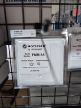
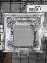
Notifier FMM-1A ULC Listed monitor modules supervise a circuit of dry-contact input devices, such as conventional heat detectors and pull stations. FMM-1A is a standard-sized module (typically mounts to a 4" [10.16 cm] square box) that supervises either a Style D (Class A) or Style B (Class B) circuit of dry-contact input devices.
NOTE: “A” suffix indicates ULC-listed model.
Features
• Built-in type identification automatically identifies this device as a monitor module to the control panel.
• Powered directly by two-wire SLC loop. No additional power required.
• High noise (EMF/RFI) immunity.
• SEMS screws with clamping plates for ease of wiring.
• Direct-dial entry of address: 01 – 159 on FlashScan loops; 01 – 99 on CLIP loops.
• LED flashes green during normal operation (programmable option) and latches on steady red to indicate alarm.
The FMM-1(A) Monitor Module is intended for use in intelligent, two-wire systems, where the individual address of each module is selected using the built-in rotary switches. It provides either a two-wire or four-wire fault-tolerant Initiating Device Circuit (IDC) for normally-open-contact fire alarm and supervisory devices. The module has a panel-controlled LED indicator. The FMM-1(A) can be used to replace MMX-1(A) modules in existing systems.
APPLICATIONS
Use to monitor a zone of four-wire smoke detectors, manual fire alarm pull stations, waterflow devices, or other normally open dry-contact alarm activation devices. May also be used to monitor normally-open supervisory devices with special supervisory indication at the control panel. Monitored circuit may be wired as an NFPA Style B (Class B) or Style D (Class A) Initiating Device Circuit. A 47K Ohm End-of-Line Resistor (provided) terminates the Style B circuit. No resistor is required for supervision of the Style D circuit.
OPERATION
Each FMM-1A uses one of the available module addresses on an SLC loop. It responds to regular polls from the control panel and reports its type and the status (open/normal/short) of its Initiating Device Circuit (IDC). A flashing LED indicates that the module is in communication with the control panel. The LED latches steady on alarm (subject to current limitations on the loop).
SPECIFICATIONS
Nominal operating voltage: 15 to 32 VDC.
Maximum current draw: 5.0 mA (LED on).
Average operating current: 375 μA (LED flashing), 1 communication every 5 seconds, 47k EOL.
Maximum IDC wiring resistance: 1500 Ohms.
Maximum IDC Voltage: 11 Volts.
EOL resistance: 47K Ohms.
Temperature range: 32°F to 120°F (0°C to 49°C).
Humidity range: 10% to 93% noncondensing.
Dimensions: 4.5" (11.43 cm) high x 4" (10.16 cm) wide x 1.25" (3.175 cm) deep. Mounts to a 4" (10.16 cm) square x 2.125" (5.398 cm) deep box.


